There's nothing that makes a dull day agog than the sight of a box at the front doorstep. Rushes of endorphins trickle through vascular cavities, eventually taking the mind to a frenetic state. Flurries of legs hurry to find the only pair of scissors in the house, which is inconveniently misplaced. Regardless, the only viable option is to release the anticipation and shred open the familiar enclosure. A bead of sweat drips from the chin and onto the only thing in plain sight.
 |
| It's beautiful. |
That's right. I managed to come across a sale for two Maxwell 2600 Farad, 2.5V ultracapacitors. And since I don't have a hybrid bus to power, the only other thing to use the capacitors for could only possibly be...
 |
| Scientific! |
Unfortunately, the capacitors are useless unless charged. After pondering about what the most efficient and safe charging system would be, I decided to make a constant-current constant-voltage charging circuit.
 |
| Relay, power switch, ballast resistor, indicator LEDs and trimmer in sight. |
 |
| One of the regulators. |
The circuit uses a 2.5A current regulator and a 5V regulator as the main components. It starts with the constant current regulator, and once the two 2.5V capacitors reach 4.5V, the charger switches to a constant voltage of 5V. Once this happens, the current starts at 2.5A and declines as the capacitor reaches 5V. A transistor is used to turn on the relay that switches from constant current to constant voltage. The transistor is connected in parallel to the capacitor, allowing the capacitor to power it while it is switching the relay. And interestingly enough, this serves a second function. If the capacitor is not connected, the voltage rises to reach 2.5A, switches on the transistor, which switches on the relay, which turns off the transistor as the transistor cannot power the relay while it is switching. This effectively creates a buzzer, notifying me if the capacitor is not connected.
The other charging indicators are the two LEDs, one hooked up to the relay and one hooked up to the capacitor. This makes it easy to see if the capacitor switches into constant voltage mode by checking to see if the green LED is on, showing that the capacitor is fully charged.
 |
| Ready! |
Once the capacitors are charged, the safety goggles and thick gloves go on, and I bring the capacitors outside. Just to see how quickly the voltage decreases, I keep the multimeter connected. The result is a fantastic luminescent display.
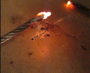 |
| Red hot screw! |
To estimate the amount of current flowing through the screw, the average energy and average voltage is used. Since power dissipated is P=IV and power stored by a capacitor is P=.5C(Vf²-Vi²)/t, these can be substituted to find the current, I, in amperes. Our new formula is I=.5C(Vf²-Vi²)/tV, where C=1300F, Vf=2.9V, Vi=4.9V, t=20s, and the average voltage V is equal to 3.9V. Our answer is an astonishing average of 130A. Obviously, this is a crude average, as voltage of the capacitors decreases over time, causing current to decrease, and the resistance of the screw increases as it heats up. Regardless, this current is remarkable!
Grant


No comments:
Post a Comment